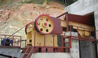
Selecting and Sizing Ball Screw Drives (letter)Selecting and Sizing Ball Screw Drives Jeff G. Johnson, Product Engineer Thomson Industries, Inc. Wood Dale, IL Thomson Fig 1: Ball screw drive is a popular linear actuator Introduction The ball screw drive is an assembly that converts rotary motion to linear motion and vice versa. The ball ...
Design of Transmission Systemswidth power rating calculations based on strength and wear considerations Parallel axis Helical Gears – Pressure angle in the normal and transverse plane Equivalent number of teeth forces and stresses. Estimating the size of the helical gears. UNIT III BEVEL, WORM AND CROSS HELICAL GEARS Straight bevel gear: Tooth terminology, tooth forces and stresses, equivalent number of teeth ...
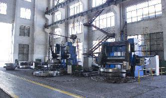
Design, Modeling and Analysis of Rotary AirLock ValveAssures maximum torque delivery 4. Design of shaft Data for calculations Weight of Air lock valve = 600kg Arm Length = 240mm Speed = 27 rpm Shear Force = 650 kg/cm2 Bending Force = 800 kg/cm2 Combined shock fatigue factors for bending (k m) = 2 Combined shock fatigue factors for torsion (K t) = 2 Power = 2 Bearing Length = 140cm Summary for Theoretical Calculations The deflection ...
Ball Screw Selection and CalculationsME EN 7960 – Precision Machine Design – Ball Screw Calculations 44 Driving Torque to Obtain Thrust 2πη F l T = a T: driving torque [Nm] Fa: thrust force [N] l: screw lead [m] η: efficiency Source: THK Co., Ltd. 3 ME EN 7960 – Precision Machine Design – Ball Screw Calculations 45 Required Thrust • The thrust is the sum of all forces acting in the axial direction. Fa =FM +Ff +Fi ...
. No. E1102m 2013 C11 · Deep Groove Ball Brgs. B4 Angular Contact Ball Brgs. B46 SelfAligning Ball Brgs. B76 Cylindrical Roller Brgs. B84 Tapered Roller Brgs. B110 Spherical Roller Brgs. B182 Thrust Brgs. B206 Needle Roller Brgs. B244 Ball Brg. Units B280 Plummer Blocks B304 Cylindrical Roller Brgs. for Sheaves B326 Balls and Rollers B346 RollNeck Brgs. (4Rows) Railway Rolling Stock Brgs. B334 Accessories for ...
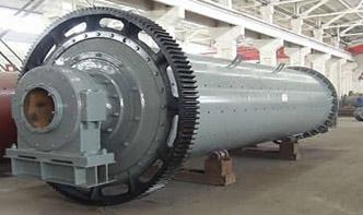
TECHNICAL NOTES 8 GRINDING R. P. KingFigure Simplified calculation of the torque required to turn a mill. RI FULWLFDO VSHHG 3RZHU Figure The effect of mill speed on the power drawn by a rotating mill. The liner profile and the stickiness of the pulp in the mill can have a significant effect on the actual critical velocity. Mills usually operate in the range 65 82% of critical but values as high as 90% are sometimes used ...
Engineering Fundamentals of Threaded Fastener Design and Analysis1 RS Technologies, a Division of PCB Load Torque, Inc. 24350 Indoplex Circle, Farmington Hills, MI 48335 USA TollFree in the USA Fax: Email:rsinfo
Bearing Load Calculationbe mathematically calculated, but calculation is difficult in many cases. A method of calculating loads that act upon shafts that convey dynamic force, which is the primary appliion of bearings, is provided herein. Load acting on shafts Load factor There are many instances where the actual operational shaft load is much greater than the theoretically calculated load, due to machin
Examples of Selecting a Ball ScrewBall Screw Examples of Selecting a Ball Screw Highspeed Transfer Equipment (Horizontal Use) Table Mass m 1 =60kg ork Mass W m 2 =20kg Stroke length S =1000mm Maximum speed V max =1m/s Acceleration time t 1 = Deceleration time t 3 = Number of reciproions per minute n =8min 1 Backlash
A GUIDE TO TORQUE VALUESA GUIDE TO TORQUE VALUES It should be understood that the subject of torque tension loading is beyond the scope of this document. The information here supplied is an acceptable guide for normal conditions; for critical appliions, however, further information and research will be necessary. In preparing this guide to torque values, the following basic assumptions have been made: (a) bolts ...
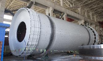
ball mill torque calculationball ball mill torque and power rating calculations pdf . Starting Torque Of Ball Mill Calculation. starting torque of ball mill calculation 813 Power drawn by ball semiautogenous and autogenous mills A simplified picture of the mill load is shown in Figure 83 Ad this can be used to establish the essential features of a model for mill power The torque required to turn the mill is given by ...
Technical Calculation / Selection Method | Ball Screws ...MISUMI eCatalog, the alog company's website supplying Linear Motion, Rotary, Transmission and Loing products of Mechanical Components for Factory Automation such as Linear Shafts, Set Collars, Linear Bushings. We provide lowpriced, highquality products. MISUMI eCatalog, the best way to procure products of Mechanical Components for Factory Automation.
SOLID MECHANICS TUTORIAL – GEAR SYSTEMS500 rev/min anticlockwise. The input power is 50 kW and the efficiency is 60%. Determine the following. i. The input torque. ( Nm) ii. The output power. (30 kW) iii. The output torque. (573 Nm) iv. The holding torque. ( Nm clockwise) 2. A gear box must produce an output power and torque of 40 kW and 60 Nm when
Calculation Of Torque For Ball MillCalculation Of Torque For Ball Mill Afghanistan calculation of torque for ball mill velletridueit central drive ball mill torque and power calculation pdf ball mills for wet and dry grinding in the minerals industry search Development Centre and powerBall mills autogenous mills and semiautogenous mills from ThyssenKrupp The ring motor features noncontact transmission of . Torque Speed ...
Mechanics and Machine Design, Equations and Calculators ... · Mechanics and Machine Design, Equations and Calculators, Design of Load Carrying Shaft With One Pulley Supported by two Bearings, Flywheel Effect or Polar Moment of Inertia, Lifting Boom, Davits Appliion and Design Equations, Large and Small Diameter Lifting Pulley / Drums, Two Lifting Lifting Pulley's Mechanical Advantage, Multiple Pulley's Lifting Mechanical Advantage Mechanical ...
Design Manual for Power Transmission BeltsMills(BallRodTube) Hoists Rubber CalendersExtrudersMills AC Motors : High Torque, High Slip, RepulsionInduction, Single Phase Series Wound and Slip Ring. DC Motors : Series Wound and Compound Wound, Single Cylinder Internal Combustion Engines, Line Shafts, Clutches. 04 Classical VBelts. The horsepower ratings recommended for standard belts of average length and with 180 degree arc of ...
Handbook of Electric Machines · with nominal torque (intersection of the blue line with the torque axis on the lefthand side) and switches the first time when the new configuration allows operating at nominal torque again. Figure 7: Influence of the rotor resistance (5) The starting torque of the squirrelcage rotor can be increased by shaping the rotor bars. Figure 8 shows ...
Ball Mill Motor Torque CalculationsCalculation Of Torque For Ball Mill Afghanistan calculation of torque for ball mill velletridueit central drive ball mill torque and power calculation pdf ball mills for wet and dry grinding in the minerals industry search Development Centre and powerBall mills autogenous mills and semiautogenous mills from ThyssenKrupp The ring motor features noncontact transmission of . Read More . How To ...
Motor Torque/Speed Curve Tutorial:::Understanding ...In the English system, calculations should be done in degrees/second, and radians/sec for SI calculations. NOTE: ... or power P. When a torque T (with respect to the axis of rotation) acts on a body that rotates with angular velocity W, its power (rate of doing work) is the product of the torque and angular velocity. This is the analog of the relation P = F·v for particle motion. Power in ...
Motor Sizing CalculationsFormulas for Calculating Load Torque Ball Screw Pulley FA m D TL · 2π i (FA m)D [ozin]..... 2i D FA m F FA m (sin cos )[oz.] ..... T FP B 0F 0P B 1 L ( ) [ozin]..... 2π 2π i F A F m m Direct Coupling FA ORIENTAL MOTOR GENERAL CATALOG 2003/2004 F3 Tec hnical Reference Standard AC Motors Speed Control Systems Stepping Motors Gearheads Linear Motion Cooling F ans Motor and F an .
DSL1200R1 COUPLINGSPower transmission mechanism produces high torque A significant feature of the FORMFLEX COUPLINGS is its flexible element, which is laminated with thin square stainless steel sheets. The holes A, C and B, D in the diagram are bolted at the hub and spacer, respectively. The torque is directly transmitted as tension from A to B and C to D through the straight side of the flexible element ...
Motor Sizing CalculationsFormulas for Calculating Load Torque Ball Screw Pulley FA m D TL · 2π i (FA m)D Linear[ozin]..... 2i D FA m F FA m (sin cos )[oz.] ..... T FP B 0F 0P B 1 L ( ) [ozin]..... 2π 2π i F A F m m Direct Coupling FA F3 Tec hnical Reference Standard AC Motors Speed Control Systems Stepping Motors Gearheads Motion Cooling F ans Motor and F an Sizing Formulas for Calculating Moment of Inertia ...
Engineering Fundamentals of Threaded Fastener Design and ...1 RS Technologies, a Division of PCB Load Torque, Inc. 24350 Indoplex Circle, Farmington Hills, MI 48335 USA TollFree in the USA Fax: Email:rsinfo
(PDF) Methodology for Calculation of Rolling Load and ...In this paper the analysis process is define by comparing the power and torque available at the input and the total power and torque required for hot rolling process. For obtaining these Mayuur S. Shelke, Prof. Kshirsagar 27 , INTERNATIONAL JOURNAL OF RESEARCH IN AERONAUTICAL AND MECHANICAL ENGINEERING January 2014. Pgs: 2734 calculations we have calculated the motor power ...
Gearbox Modeling and Load Simulation of a Baseline 750kW .analysis calculations; and poor communiion between wind turbine designers, gearbox suppliers, and bearing providers. This report discusses determining a method for revealing the missing loading conditions that should be factored into the gearboxdesign process. This objective is achieved by development of a number of analytical models that sequentially increase in complexity, and which are ...